Ever wanted to give more visual appeal to your 6100? You can try changing the LED light from the typical green to virtually any color of LED you want.
I did this just days after seeing it done both on a Japanese website about modifying the 6100 and a picture of a 6100 with the blue LED on Danaquarium.com.
Below is a 'guide' of how i accomplished this.
WARNING: I take no responsibility in what you do to your 6100 or how you do it. This particular guide is written by a college student with NO 'professional' soldering experience. Proceed at your own risk.
I recommend the Blue LED from RadioShack (model: 276-316) since that is the one I'm using for this 'installation guide'. It is a 5mm LED, that uses 3.7 volts and, in terms of brightness, is rated at 2600mcd (milli candela).
Among the other items you'd need are:
1) any 15-30 watt soldering iron (set at 15 watts)
2) soldering paste
3) some lead (try to use the lead solder that is intended for electronics and not the one used for plumbing)
4) Kronus "Helping Hands" (to hold the LED and LED cable/wires in place)
5) heat-shrink tubing
6) utility knife or box cutter
7) hair dryer
8) tissue paper (to protect the LED and the LED cable from getting crushed, punctured or ruined by the clamps of the Kronus "Helping Hands")
9) wire cutter
10) flat-head screwdriver
11) PATIENCE and steady hands... obviously you don't want to break the thing....
Here are the steps:
Remove all of the internal components from the 6100 in the following order. This includes:
1) The top case cover. Lift up the 2 tabs on the back of the case to open it.
2) The hard drive
Remove the EMI (electro magnetic interference) shield. Unplug the power connector lead and the SCSI data cable. Then slowly and carfully pull out the hard drive.
3) The CD drive
Remove the EMI (electro magnetic interference) shield. Unplug the second power connector lead, the SCSI data cable, and that smaller third plug (which i believe is for sound output).
4) The Floppy drive.
This was tricky for me at first since removing it is NOT the same as the first two drives. To remove the EMI (electro magnetic interference) shield, you MUST remove the CD drive in order to slightly pry open the protective, plastic tabs closest to the power supply that locks the floppy drive in place. Once the drive is slightly out of the chasis, unplug the data cable.
5) The power supply unit.
Unscrew the PSU and uplug the final power lead that connects to the motherboard. This may require you to use a flathead screw driver to actually pry it open. If you over-bend it while prying it, making it loose, it should be okay, just so long as you don't rip the whole thing out of the motherboard. Also, this part will require a significant amount of physical strength to pull out.
6) The motherboard.
Remove any G3 upgrade cards or such, and memory upgrades. Unplug the final plug of the SCSI data cable from the motherboard (it may help you to simply lable that particular portion of the cable that goes to the motherboard with a black permanent marker). Unplug the small , brown, LED cable that is underneath the hard disk drive bed. Unplug the speaker cable that's underneath the CD drive bed. Unscrew the tall white plastic column with the screw driver to remove it, and unscrew the exposed screw which is closest to the CD drive. In total, there are only two screws for the motherboard. You can rest the motherboard on a clean piece of cardboard or paper on the table so as to not cause any static or dust damage to it's components.
7) The plastic HDD/CD/Floppy drive holder.
This piece of sh!t is physically -THE HARDEST- part to pull out. I recommend following the guide available at AppleRepairManuals.com to get the details. It's a .PDF file so you'll need to use Adobe Reader to view it. If it's not available there for any reason, do a Google search for "Power Macintosh Service Manual".
8) Remove the LED cable from the 3-drive holder.
NOW here comes the fun part: Changing the LED.
1) Gently splice open the rubbery heat-shrink tubing that covers each wire between the LED bulb and the two wires.
2) Place the LED cable on one of the clamps in the Kronus Helping Hands tool. I recommend wrapping some tissue paper over the wires before putting it in the clamp so as to not puncture the wires.
3) Unsolder and remove the old LED. Do NOT keep the soldering iron's tip on the solder points too long since prolonged exposure to the intense heat will damage the LED. (In case you should ever want to revert it back to the old LED....)
4) Cut the anode and cathode of the new LED to match the length of th old LED.
5) Wrap the new LED in some tissue paper or a rubber band before putting it in the "Helping Hands" clamp so it won't get cracked.
6) Put some heat-shrink tubing over each wire BUT slide it several inches past the exposed parts of each wire so that you can slide it over the soldered connection when you are -CERTAIN- the LED works.
7) Solder the new LED to the LED cable. It helps to know this tip: "Black wire to cathode, Red wire to annode." The "a" in the picture is the annode, and "k" is the cathode. You must also make sure that not too much of the molten lead gets in between the wire and the anode or cathode or else you wont get a good enough connection when electric current goes through.

8) TEST the newly soldered LED. In order to do this, temporarily reinstall the motherboard and power supply unit back into the 6100 and reconnect the power lead from the PSU to the motherboard. Then reconnect the LED cable to the motherboard. Plug in the 3-pronged power cord to the power supply and then to an available power outlet. Then, turn on the power. If the LED cable lights up, then you're good to go.
9) Unplug the PSU from the power outlet, unplug the power cord from the PSU, unplug the power lead between the PSU and the motherboard, remove the LED cable and then remove the motherboard.
10) Slide the heat-shrink tubing up and towards the new soldering points so as to cover it as completely as the old tubing did. And using a hair dryer, apply just enough heat to seal the tubing. (it doesn't have to be -too- tight)
Here is the reinstallation process (IN ORDER).
1) Reconnect the LED cable to the 3-drive holder.
2) Reinstall the 3-drive holder to the metal chasis of the 6100.
If the two plastic locking teeth underneath the CD drive section of the holder breaks off, it's actually OKAY. Just proceed with the reinstallation.
3) Reinstall the motherboard
4) Reinstall the Power Supply Unit
5) Connect the PSU lead cable to the motherboard
6) Connect the tiny LED cable connecter and the tiny speaker connector to the motherboard.
7) Reinstall the SCSI data cable to the motherboard.
8) Reinstall the Floppy drive, then the CD drive, then the hard drive in that order. Then reconnect the data, power and sound cables as described above in the internal component removal process. Don't forget to reinstall the EMI shields as well. (I didn't reinstall the EMI shields on my 6100, but you -SHOULD-, just to be on the safe side).
9) Reinstall any RAM upgrades or any upgrade cards to the motherboard.
10) Close the case, reconnect all the external cables, and power it on!
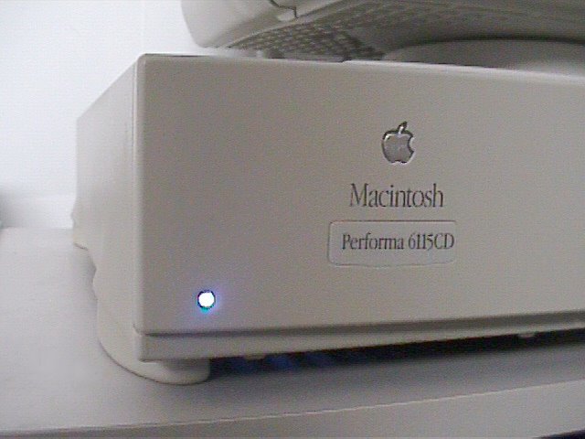
Here's some before and after pics from Danaquarium.com.

